FLB 14.2 – Osborne Reynolds Demonstrator

The goal for this apparatus is to reproduce the experiment designed by Osborne Reynolds visualizing laminar, transitional and turbulent flows, and establishing the Reynolds number that corresponds to each one of them.
Description

The equipment is designed to be operated on the hydraulic bench (FL01.4, FL FL01.5 or 01.6).

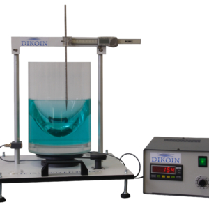
A flow of water mixed with ink in a certain dose is pushed through a needle placed at the entry into a glass tube.

Depending on the flow rate passing through the tube, it can be seen how the ink mixes or not with the water, making a neat line in the case of a laminar flow, or getting mixed with the water in transitional regimes. When it gets to the point of turbulence, the ink will be thoroughly mixed with the water, and it will not be possible to tell them apart.

Learning Objectives
The practices and experiences that can be performed with this equipment are:
    • Study, visualization and determination of the Reynolds number of a laminar regime.
    • Study, visualization and determination of the Reynolds number of a transition regime.
    • Study, visualization and determination of the Reynolds number of a turbulent flow.
Technical Data
Bores:
    • Calibrated glass tube:
      • Internal diameter: 12 mm
      • External diameter: 17 mm
      • Length: 700 mm
 
INK:
    • Acrylic ink, diluted in water: 20% ink.
ELEMENTS
    • Dye deposit 0,5l.
    • Dye regulating valve.
    • Main tank 2,3 l aprox.
    • Overflow.
    • Glass spheres.
    • Out of clean water.
    • Calibrated glass tube.
    • Flow control valve.
    • Bubble level.
    • Out of water in glass tube.
    • Connection of water inlet.
    • 1 Bottle of acrylic paint.
    • 3 Ink dispensing needles.
Requirements
  • Hydraulic bench FL 01.4, FL 01.5 ó FL 01.6