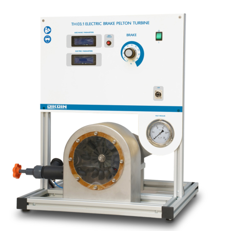
TH 04.1 – Autonomous Electric Brake Pelton Turbine

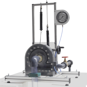
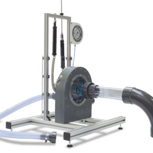
The TH 04.1 equipment simulates a small-scale installation with a Pelton turbine.
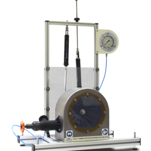
Description

The turbine housing is transparent so that can be viewed as the turbine uses the inertia that transfers a water jet which propels the recoil principle.

Regulating valve has water inlet, which allows working with different flows as required.

The braking system by electric brake allows working at different speeds.

The equipment is computerized which means that the inlet pressure to the turbine, the flow, the braking torque, ultimately, all variables are displayed in the integrated team structure computer.

Learning Objectives
  • Turbine characteristic curves:
    • Torque – speed (M-n).
    • Brake power – speed (Pe- n).
    • Performance – speed (h – n).
    • Torque – U (M-U).
    • Brake power – U (Pe- U).
    • Performance – U (h– U).
  • Iso-performance curves.
Technical Data
Brake Type:
    • Electric brake.
Turbine:
    • Type: Pelton
    • Number of blades: 16.
    • Wheel diameter 124 mm.
    • Bucket depth 14 mm.
    • Jet diameter 10 mm.
    • Shaft diameter 16 mm.
    • Rated speed 1,900 rpm
    • Transparent front plate to visualize the Pelton wheel working.
Structure:
    • The equipment is provided on an aluminum frame, with tank and pump, in which the required flow for the turbine is generated.
Electronic components:
    • Pressure transducer.
    • Rpm direct detection sensor.
    • Load cell for measuring the torque.
    • Data acquisition module.
Other elements:
· Computer with touch screen attached to the main control panel.
    • The system is controlled with the computer (not only data adquisition).
Requirements
  • Power supply: 230V / 50 Hz.

NOTE:The image shown is indicative.

This post is also available in: ES