ST 03.1 – Continuous Beams
The objective of this equipment consists of the study of the deformation in the plane, of continuous beams under the action of loads.
Description
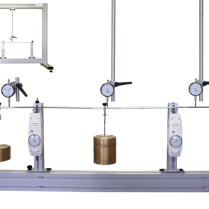
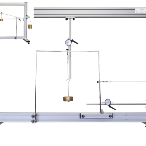
The equipment includes a clamping end and articulated sliding supports with dynamometer.
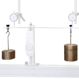
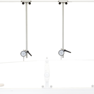
The deformation is measured by means of 3 dial gauges that can be placed in any point of the beam. These deformations are the answer of the system to the different applied loads.
The placing of the structure under load is obtained through 2 load systems with weights, whose maximum load is 12 kg, having weights of different masses, from 0.5 to 2.5 kg.
The equipment is provided with 2 beams of different sections, 20x5mm and 20x3mm.
Learning Objectives
- Study of the deformation of a continuous beam.
- Study of supports:
- Clamping
- Articulated sliding support
- Comparison between calculated and measured displacements.
- Application of the superposition principle.
Technical Data
Beams
- Material: Polished Stainless steel AISI 304
- Cross-sections:
- 1x 20×5 mm
- 1x 20×3 mm
- Creep strength: 310 MPa (45 KSI)
- Maxima Resistance: 620 MPa (90 KSI)
- Modulus of elasticity: 200 GPa (29000 KSI)
- Density: 7,8 g/cm3 (0.28 lb/in3)
Weights
- Material: Bronze
- Minimum precision of the mass: ± 2%
- Units and mass:
- 3x 2.5 kg
- 3x 1 kg
- 2x 0.5 kg
- 2x stainless steel Hooks for positioning of weights.
System of measurement of displacements
- 2 systems of measurement of displacement with dial gauge.
- Measurement range: 0 to 25 mm
- Appreciation: 0,01mm
Load positioning flange
- 2 load positioning flanges.
- Material: Stainless steel.
Sliding articulated support with dynanometer
- 2x articulated sliding supports with dynanometer.
- Maximum load: 100 N
- Recovery system to zero-ground , under the application of load.
Clamping support
- 1x clamping support.
- Fixation of beam by means of screws with plastic nuts (it is not necessary to use tools).
Requirements
- The mounting frame ST 01.1 is necessary for this equipment.


