TH 03.2 – Electric Brake Francis Turbine
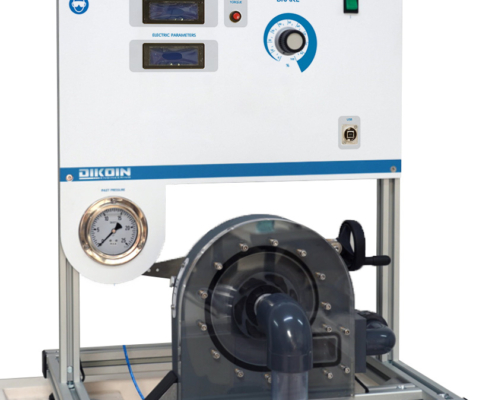
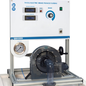
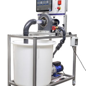
The TH 03.2 equipment simulates a small-scale installation with a Francis turbine or reaction.
The equipment is designed for the study and display both the behavior and the characteristics of a Francis turbine.
Among its most notable features include the turbine housing is transparent so you can see how the water flow turns the wheel. In this case, besides the rotation of the wheel, the movement of the vanes guide the distributor with which the flow regulation turbine inlet is achieved is also observed.
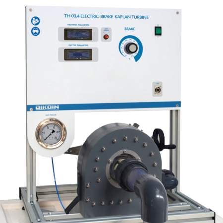
The braking system with electric brake allows to work at different speeds in a convenient and simple way. The rotational speed of the engine control by a rheostat included in the top control module, where, in addition, through the various indicators of the system, you can display all variables that come into play in transforming energy.
Regulating valve has water inlet, which allows working with different flows as required. Pressure turbine inlet is read in a vacuum gauge arranged on the structure.
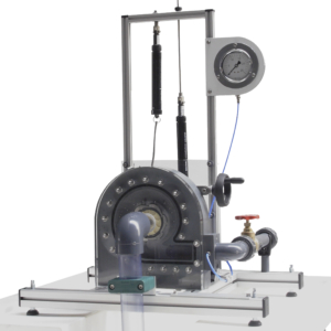
Pelton turbine.
- Torque – speed (M-n).
- Brake power – rotation speed (PE – n).
- Performance – speed (h – n).
- Torque – U (M-U).
- Brake power – U (Pe- U).
- Performance – U (h – U).
- Bourdon type with glycerin 0-25 m.c.a.
- DC generator
- Rated speed: 1950 rpm
- Rated power: 45 W
- Wheel diameter: 60 mm.
- Number of fixed blades 12.
- Number of guide vanes: 6.
- Rated speed: 2000 r.p.m.
- Interior diameter of the drive pipe = 27,2 mm.
- Interior diameter of the outlet pipe = 27,2 mm.
- Load cell.
- Speed sensor.
- Electronic indicators readings.
- Hydraulics Bench FL 01.4, FL 01.6 or FL 01.7
- Power supply: 230V / 50Hz.

