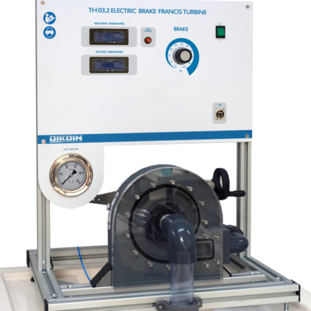
TH 03.1 – Electric Brake Pelton Turbine
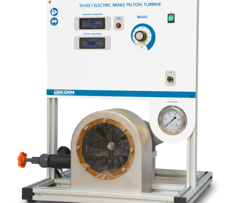
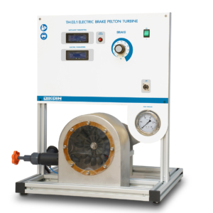
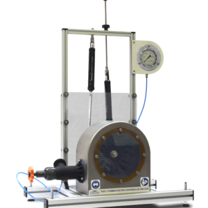
The TH 03.1 equipment simulates a small-scale installation with a Pelton turbine.
Description
The turbine housing is transparent so that can be viewed as the turbine uses the inertia that transfers a water jet which propels the recoil principle.
Through various system indicators, you can view all the variables that come into play in transforming energy.
The braking system by electric brake allows working at different speeds in a simple and effective way.
The equipment is designed for the study and display both the behavior and the characteristics of a Pelton turbine.
Learning Objectives
- Turbine characteristic curves:
- Torque – speed (M-n).
- Brake power – speed (Pe- n).
- Performance – speed (h – n).
- Torque – U (M-U).
- Brake power – U (Pe- U).
- Performance – U (h– U).
- Iso-performance curves.
- Set performance turbine electric generator.
Technical Data
Pipe dimensions:
- Drive pipe outside diameter: 32 mm
- Nozzle inside diameter: 10 mm
Pressure gauges:
- Bourdon type, glycerin-filled, 0–25 mH₂O
Electric brake characteristics:
- DC generator
- Rated speed: 3000 rpm
- Rated power: 1000 W
- Turbine characteristics:
- Number of blades: 16
- Runner diameter: 124 mm
- Bucket depth: 14 mm
- Jet diameter: 10 mm
- Shaft diameter: 16 mm
- Rated speed: 1000 rpm
- Runner material: Polyamide
Other data:
- Speed sensor
- Load cell
- Data displayed on electronic panel
Note:
- The equipment is supplied with a complete laboratory manual.
- The system can be connected to a computer via USB to record all data directly into tables.
Requirements
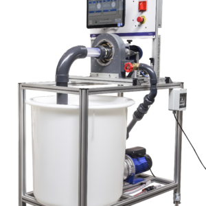
- Hydraulics Bench FL 01.4 or FL 01.5 or FL 01.6 .
- Power supply: 230V / 50Hz.
NOTE:The image shown is indicative.

