FL 27.2 – Flow Networks
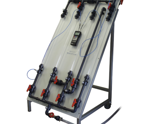
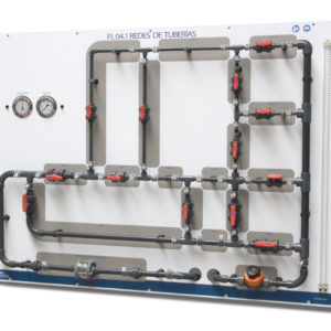
The “Flow networks” equipment reflects in scale the problem that usually appears for the calculation of pressures and flows in pipes that interconnect each other. These pipes usually have different diameters and lengths and form different systems (serial, parallel, mesh …) which severely complicates the calculation.
Description
The “Flow networks” equipment reflects in scale the problem that usually appears for the calculation of pressures and flows in pipes that interconnect each other. These pipes usually have different diameters and lengths and form different systems (serial, parallel, mesh …) which severely complicates the calculation.
These pipe interconnections are known as flow networks. An example of this could be the village water supply network or the fire-fighting system of a building.
It is essential to know the behavior of these pipes and the pressure and flow readings they record for their good design. For example, by modelling the system we can know at any moment the flow rate that flows through each of the pipes.
With this equipment will be possible to realize the experimental practices that allow us to verify the behavior of the network of flow in front of diverse situations. The equipment consists of a series of transparent pipes with different diameters, as well as a series of valves placed in strategic points of the network. The quick connections that the equipment has, allow to interchange the different pipes. This, together with the actuation of the valves, allows the different network study configurations to be achieved quickly.
Learning Objectives
The objectives to be achieved with the implementation of these practices are the following:
- Modeling of the pipe network. Calibrating each and every one of the components or sections, so that at all times we know the flow that circulates through them.
- Measurement and checking of the loss of load of different pipe arrangements in series.
- Calculation and verification of the flow rates in various pipe systems in parallel.
- Calculation and verification of the distribution of flows and their sense in a meshed system of pipes.
- Checking the behavior of an installation when placing another pipe in parallel.
Technical Data
Pipe sections:
- Pipe 700 mm Ø14 mm
- Pipe 700 mm Ø10 mm
- 2x Pipe 700 mm Ø9 mm
- Pipe 700 mm Ø6 mm
*Inner diameters.
Manometric intakes:
- The equipment has 12 manometric intakes.
- In all pipe sections the gauge is 40 mm from the three-piece connection.
Manometer:
- Electronic differential pressure gauge (±7000 mbar)
Requirements
- Hydraulic bench FL 01.4 or FL 01.5 or FL 01.6

