FL 12.1 – Flow Through Orifices

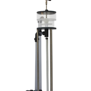
The FL12.1 equipment has been designed for the study of the contraction that occurs when a jet of fluid passes through an orifice.

Description

Its design is aimed at making teaching and learning easy thanks to its three differently-shaped nozzles. This enables a variety of conditions to carry out the tests.

The unit is equipped with a Pitot tube to measure the velocity of the fluid being discharged through the outlet.

In addition, the equipment has a measuring instrument of the jet diameter, which can be regulated, obtaining results of a greater accuracy.

Finally, this apparatus includes a water column manometer for the measurement of both the water level in the tank and the velocity of the water jet.

Learning Objectives
  • Determination of contraction and velocity coefficients. Calculation of discharge coefficient.
      • Output through orifices.
      • Output through nozzles.
  • Determination of the discharge coefficient by the measurement of the flow.
      • Output through orifices.
      • Output through nozzles.
  • Calculation of the previous sections for different flows.
  • Comparison of the emptying time of a tank for different initial heights.
Technical Data
  • Tank:
      • Cylinder tank of Ø200 x 430 mm.
      • Maximum height of water 410 mm.
    Accesories:
      • Output hole where the 30 mm accesories are placed.
        • Nozzle Ø 10 mm of straight output.
        • Nozzle Ø 10 mm of 45º output.
        • Nozzle Ø 10 mm of diaphragm output.
Requirements
  • Hydraulic bench FL 01.4 or Hydraulic Group FL 01.1 + Flow meter.

This post is also available in: ES