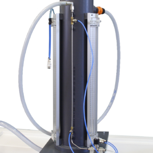
The objective of this team is the visualization and study of the formation of free and forced vortices. Is called Forced Vortex to the rotation of a fluid that moves like a solid with respect to an axis. By definition, in the forced vortex each fluid particle has the same angular velocity.
With this equipment the creation of a forced vortex is achieved by the entrance of water through the nozzles that, with a certain inclination, get the beginning of the movement of a propeller. This propeller rotates the fluid forming the curve of the parabola under study. Once the vortex is obtained, the parabola described can be represented by the measuring rods. These allow you to take the height of the parabola for each point at a fixed radial distance.
The Free Vortex is one of the elementary types of irrotational flow. This movement is distinguished from the forced vortex in that, each particle moves in a circular path at a rate that varies. This variation will be inversely proportional to the distance to the center of rotation. In this case, the other pair of nozzles will be responsible for getting the fluid to the reservoir. The inclination of those allows the formation of the free vortex.
Different outlet nozzles are available with which we analyze the influence of the outlet diameter on the described vortex, as well as pitot tubes, with different tapping radii, with which the pressure recorded readings can be taken for different depths.
In addition, the caliper accessory allows to extract the readings of the diameter of the vortex described for each depth of the same, thus being able to represent the result graphically.
The possibility of regulating the flow, both inlet, with the hydraulic bench impulsion valve, and outlet, with the ball valve, allows to establish the best flow rate for visualizing the vortex in each practice.