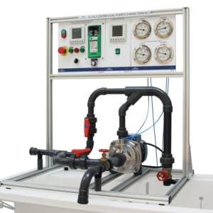
TH 01.1 – Friction Brake Pelton Turbine

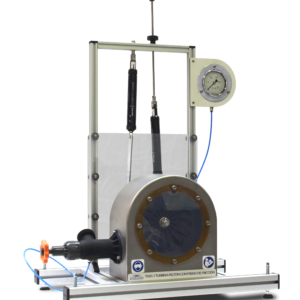
The TH.01.1 equipment simulates an instalation in a small scale with a Pelton turbine. It has been designed with special emphasis on the didactic aspect of the same, being able to observe at all times the operation of the system and the different components that constitute it.

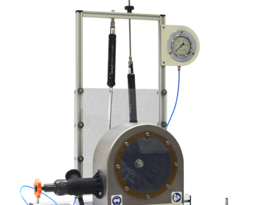
Description

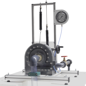
The turbine housing is transparent so that you can see how the turbine uses the inertia that transfers a jet of water, which drives it by the principle of recoil.

The equipment is endowed with different variable components, which allows to vary the facings that affect the mechanism and thanks to it to be able to realize different tests for a better understanding of the student.

It has a regulating valve for water inner, which allows to work with different flow rates as required.

Regarding to the braking system, it is made up of dynamometers that allow the braking force to be operated at different speeds.

Learning Objectives
  • Characteristic curves of the turbine:
    • Torque – rotational speed (M-n).*
    • Power to brake – rotational speed (Pe- n).*
    • Efficiency – rotational speed (h– n).*
    • Torque – U (M-U).
    • Power to brake – U (Pe- U).
    • Efficiency – U (h– U).
  • Isoefficiency curves.
Technical Data
Manometer:
    • Bourdon type with glycerin from 0 to 25 m.c.a.
Braking type:
    • Braking with Friction Brake.
Turbine:
    • Type: Pelton.
    • Number of blades : 16.
    • Diameter of the impeller 124 mm.
    • Depht of the spoon 14 mm.
    • Jet diameter 10 mm.
    • Shaft diameter 16 mm.
    • Nominal speed 1.000 r.p.m.
Dynamometers:
    • 2 x Dynamometer 5 Kg x 25 gr.
Inner diameters:
    • Impulsion pipe Øexterior = 32 mm.
    • Entrance nozzle Øinterior = 10 mm.
Dimensions of the equipment:
    • Width x length x height: 600 x 440 x 700 mm.
Requirements
  • Hydraulic Bench FL 01.4 or FL 01.5 or FL 01.6
* A tachometer or stroboscope is required for measuring the speed of rotation.