FL 18.2 – Losses in Elbows

In order to calculate the secondary load losses produced by the fittings of an installation, we take data of the difference of pressures between the gauges upstream and downstream of the element to be measured, in addition, we must subtract the existing primary load losses due to the straight sections of a pipe.
Description
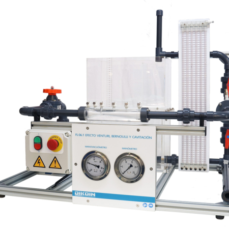
When we want to obtain the pressure loss that occurs between two pressure ports located in pipes of different diameter, we must take into account that not all the difference of static pressures read corresponds to losses of load, that part is due to the transformation of static pressure in dynamic pressure by the increase of the speed.
The equipment has all possible configurations of 90 ° elbows, in addition to widening and abrupt narrowing, and a gate valve. These load losses are read simultaneously by means of a water column multimanometer, which allows to visualize with maximum clarity the difference between the different types of bends, and additionally, of widening and narrowing, and valve.
In addition, the equipment has an electronic differential pressure gauge, which allows the measurement with a greater range, of the pressure loss produced in the gate valve with different openings.
Learning Objectives
The objectives that are intended to be achieved with the design of this didactic equipment are the following:
  • Checking the relationship between load losses and fluid velocity in the pipe.
  • Measurement and verification of the secondary losses of load that occur in elements of installations, such as:
      • Elbows of 90º
      • Curves of 90º
      • Long curve of 90º
      • Elbows of 45º
      • Abrupt narrowing
      • Abrupt widening
      • Gate valve
  • Calculation of the loss coefficients “K” corresponding to each of the elements mentioned above.
  • Use of different types of manometers:
      • Water column
      • Electronic differential
Technical Data
Pipe diameters:
    • Main pipe:
Øinterior = 21,2 mm. ; Øexterior = 25 mm.
    • Abrupt Narrowing/Widening:
Øinterior = 27,2 mm. ; Øexterior = 32 mm.
Components to study:
    • Long curve 90º
    • Abrupt narrowing
    • Abrupt widening
    • Usual elbow 90º
    • Short curve 90º
    • Gate valve
    • Straight elbow 90º
Manometers:
    • Water column multimanometer of 12 tubes and 440 mm
    • Electronic differential manometer
Additional characteristics:
    • The equipment has a hand pump for adjusting the reading height on the multi-tube manometer.
Requirements
  • Hydraulic bench FL 01.4 or FL 01.5 or FL 01.6 or Hydraulic group FL 01.1 + Flow meter.