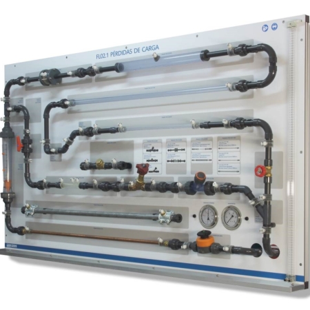
This equipment counts on a vertical pipe, in which we make the readings of the loss of load produced for different flows; Flow rates that we obtain through the regulating valve with which the equipment counts.
The study of the different regimes is achieved by modifying the way in which the water reaches the test pipe, so that, in order to achieve the laminar regime, the pipe is fed from a tank of constant height while for the turbulent regime the supply will be made directly from the water supply equipment.
For the readings of upstream and downstream pressures of the test line, we have two differential pressure gauges, one of water and one of mercury.
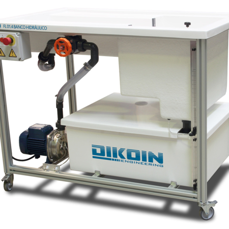
Measurements of the flow rates obtained with the control valve are performed using the supplied test tube or the volumetric reservoir of the hydraulic bank (required), which also studies the relationship between the pressure drop and the fluid velocity.


 FL 18.1 – Secondary Energy Losses