FL 17.1 – Pipe Friction

The objective to be achieved with this equipment is the study of primary pressure losses produced along a pipeline in both laminar and turbulent regimen.
Description

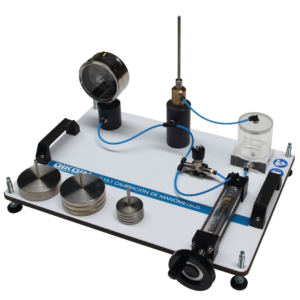
This equipment has a horizontal pipe in which perform readings of the pressure loss produced for different flow rates. It also has, with the possibility to study the friction in the same pipe for both laminar and turbulent regime.

To get this last, we feed pipe from a tank of constant height. For readings of upstream and downstream of the pressure test pipe, we have two differential pressure gauges, one of water and other of mercury.

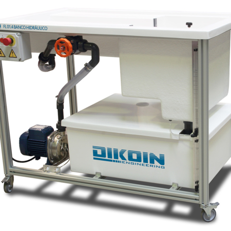
For regulation of the flow use two valves, one located at the begin of the installation and another place at the exit of the test pipe. The flow through into the pipe is measured using the volumetric tank of the hydraulic bench.

Learning Objectives
Experiments and experiences that can be realized with this equipment are as follows:
    • Determination of the primary loss of pressure produced in a pipe in laminar flow.
    • Determination of the primary loss of pressure produced in a pipe in turbulent flow.
    • Determination of friction factor.
    • Determination of the critical Reynolds number.
Technical Data
  • Charge tank 150 mm of diameter by 500 mm long.
  • Elevation head maximum to laminar regime is 900mm.
  • Inside diameter of the pipe test is 3 mm.
  • Length between survey in the test pipe 500mm.
  • Manometer of water column , measuring range 500 mm ca.
  • Digital differential manometer, measuring range ±7000 mbar.
Requirements
  • Hydraulic Bench FL 01.4.

This post is also available in: ES