FL 04.1 – Pipeline Networks
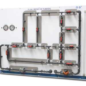
The pipeline networks equipment FL 04.1 has been developed for the study and analysis of the flow through pipe networks.
During the design we’ve thought on a complete and flexible equipment, so that the user can study the higher possible number of configurations and as complex or simple as they wish.
The change operation settings is quick, clean and simple, with no opening or closing valves, without installing or removing any pipe or fitting.
To avoid water leakage from the circuit, and having to work with many manometer tubes, the facility has dual shutter pressure taps which do not leak water when connecting or disconnecting.
So, we have a complete equipment that covers all configurations that can occur in a pipe system, which also has the opportunity to learn from the most complex to the simplest system, all in an easy and simple operation and null maintenance.
A wide range of practices and experiences can be performed with this equipment, some of which are listed below:
Modeling the piping. Calibrating each and every one of the components or sections, so that at all times know the flow through them.
Measurement and testing of the pressure drops and flow equivalent service pipes fed by an extreme route.
- With outflow.
- No outflow.
Measurement and testing of the pressure drops and flow equivalent service pipes fed route at both ends.
Measurement and verification of losses and provisions equivalent diameters of different pipes in series.
- With 2 different diameters.
- With 3 different diameters.
- With 4 different diameters.
Calculation and testing of the flow distribution in various piping systems in parallel.
Calculation and verification of the flow and pressure throughout the various types of existing networks:
- Branched network.
- Meshed network.
- Mixed network.
Using a diaphragm as measuring element.
- Checking the working pressure along the installation.
- Using different types of gauges:
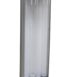
- Water column.
- Electronic differential.
- Bourdon.
- Manometer.
- Hand-gauge.
Calculating and drawing the characteristic curve of the feed pump of the installation.
- Pipe diameters:
- Pipes Group A
- Øinner = 21,2 mm
- Øexternal = 25 mm
- Pipes Group B
- Øinner = 20,6 mm
- Øexternal = 22 mm
- Pipes Group C
- Øinner = 13,8 mm
- Øexternal = 15 mm
- Pipes Group D
- Øinner = 45,2 mm
- Øexternal = 50 mm
Pressure tappings:
- In all the stretches the pressure tapping is at 40mm from the nearest accessory.
- All the conections are fast and double obturation.
Manometers:
- Water column manometer, range 1 mwc.
- Electronic differential pressure manometer (±7000 mbar)
- Bourdon type manometer, range 0 / 25 mwc.
- Bourdon type mano-vacuometer, range -76 cm Hg / 25 mwc.
Dimensions:
- 2.000 x 1300 x 200 mm.
- Hydraulic bench FL 01.4 or Hydraulic Group FL 01.1.


