FL 18.1 – Secondary Energy Losses
Description
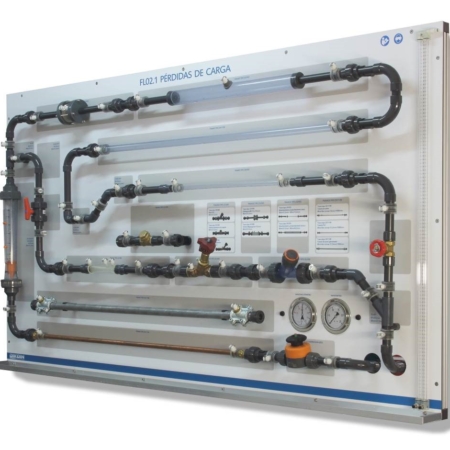
This installation for the study of the energy losses has elements such as; elbows of different diameters at 90º and 45º, tees, widening, narrowing, different types of valves (ball, gate, diaphragm, non-return,…) with upstream and downstream pressure tappings arranged for determination of the head loss between them, produced with different flow rates. It also has straight sections of pipe, which allows the study of the primary loss generated in it.
All pressure taps have quick plugs double sealed. The equipment has a water differential manometer of 1000 mm and an electronic differential manometer for the measurement of the resulting pressures.
Learning Objectives
- Measurement and checking of primary head losses occurring in a straight section of PVC pipe with a diameter of 21.2 mm.
- Checking the relationship between load losses and fluid velocity in the pipe.
- Measurement and verification of the secondary losses that occur in elements of installations, such as: elbows, tees, widenings and valves.
- Calculation of the loss coefficients “K” corresponding to the elements mentioned above.
- Use of different types of manometers:
- Water column.
- Electronic differential.
Technical Data
- Aluminum frame with adjustable height feet.
Hydraulic circuit:
- 90º elbow Ø 25 mm.
- 90º elbow Ø 16 mm.
- 45º elbow Ø 25 mm.
- Curve of 90º Ø 25 mm.
- Tee of 90º Ø 25 mm.
- Tee of 45º Ø 25 mm.
- Widening and abrupt narrowing Ø 25 mm to Ø 50 mm.
- Widening and soft narrowing Ø 25 mm to Ø 16 mm.
- Gate valve.
- Ball valve.
- Membrane valve.
- Non-return valve.
- Straight pipe section Ø 25 mm.
Measurement of pressures:
- Electronic differential manometer.
- Water column manometer of 1000 mm.
Requirements
- DIKOIN Hydraulic Bench.