EN 01.5 – Stand Alone and Network Connected
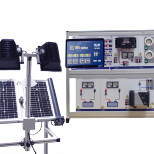
The equipment EN 01.5 reproduces a scale, complete photovoltaic solar installation. It has been designed with special emphasis on the didactic aspect. It offers the opportunity to observe all the components of a real photovoltaic solar installation and its layout.
It is supplied with adapted cables to connect and disconnect the components of the installation in different ways, so allowing to observe and analyze the operation of the connected panels in series, parallel, with batteries in series or in parallel, with direct exit in DC or AC, working standalone or connected to the network.
The equipment is supplied with metering devices for the variables necessary to analyze the characteristics of the panels and their behavior. Likewise, it has a pyranometer that indicates the intensity of solar radiation that affects the panels, with tension and current meters to show to the generated voltage and its intensity.
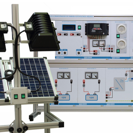
Additionally, it has tension and current meters in each one of the batteries to indicate the state of these and the direction of the current, if they are being loaded or contributing load, and it also has a metering device that shows a complete description of the obtained alternating current after the standalone inverter.
The grid connected inverter is implemented with software where the parameters of generation can be observed. In order to feed the grid-connected inverter, there are 3 panel simulators, with power regulation and tension and current metering devices.
- Study of the operation of a photovoltaic solar installation.
- Isolated panels.
- Modules connected to batteries.
- Operation with different types of loads in DC.
- Conversion of DC to AC.
- Operation with different types of loads in AC.
- Operation stand alone and connected to the grid.
- Efficiency of the installation.
- Determination of the characteristics of the solar modules.
- Current – Voltage Curve.
- Current in short circuit.
- Voltage of open circuit.
- Curve Power – Voltage.
- Curve Power – Resistance of load.
- Maximum power generated.
- Form factor.
- Efficiency.
- Influence of the tilt angle and the intensity of solar radiation in the generated energy.
- Determination of the characteristics of the modules connected in series.
- Determination of the characteristics of the modules connected in parallel.
- Study of the behavior of the solar modules in diverse conditions of operation.
- Isolated panels.
- In parallel with different loads.
- In series with different loads.
- Connected panels to batteries in series.
- In parallel with different loads.
- In series with different loads.
- Connected panels to batteries in parallel.
- In parallel with different loads.
- In series with different loads.
- Isolated panels.
- Photovoltaic modules: 2 photovoltaic modules of 20Wp.
- Pyranometer for the measurement of the solar intensity.
- Charge controller: Charge controller with operation at 12 or 24V CC, and max. current=10A. Max. input voltage= 45V.
- Batteries: 2 Batteries 12V 10Ah.
- Inverters:
- Sine wave inverter: 200 VA stand alone inverter, with single-phase output.
- Sine wave inverter 230V/50Hz, 600W to connect to single-phase network.
- Emulators of solar modules:
- Emulator of solar module of 24V 10A máx., with intensity regulation.
- Emulator of 2 solar modules of 12V 10A máx., with independent regulation of intensity.
- Single-phase network analyzer with indication of active, reactive and apparent power, current, voltage, frequency, power factor, etc.
- 6x Analogue voltmeters.
- 4x Analogue current meters.
- 2x Analogue current meters with positive and negative measurement (centered zero).
- Measuring unit with LCD screen, which simultaneously shows voltage and current values of the solar panels, and the solar intensity (pyranometer).
- 12Vdc lamps and 220Vac lamps.
- Rheostat for analysis of the voltage-current graph in the solar modules and comparison with the specifications. It allows parallel or series connection.
- Protection module for connection to the grid.
- The equipment is provided with a complete step by step guide.
- Photovoltaic modules Structure: 895x650x1740 mm.
- Electric modules structure: 512x1090x824 mm.
- Input: 230V/50Hz.