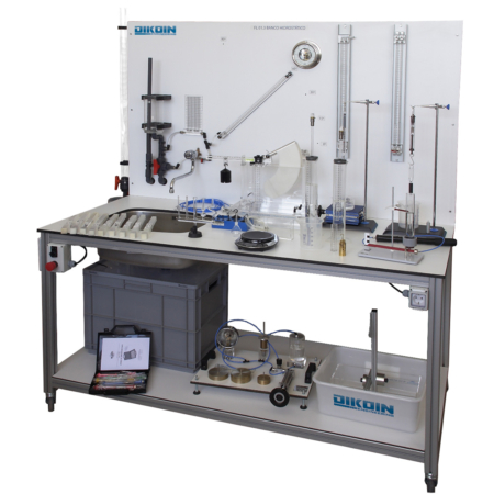
FL 02.1 – Losses in Pipes Panel
The FL02.1 equipment has been designed for the study of both friction losses in pipes, and the losses of characteristic elements of facilities such as; fittings, valves and measuring elements.
The equipment is designed to be as flexible as possible and can be built into the new fittings and straight pipe of different materials and roughness. The change operation is simple and clean, it is only necessary to use the quick links to unscrew the original section and replace with the new.
The channel on the bottom of the panel’s mission is to collect the residual water left in the pipes, so that no wet adjacent equipment and enabling this work is to make the students themselves.
In this same line to avoid water leakage circuit, installing pressure taps has called “ecological”, which does not leak water when connecting or disconnecting the gauge jacks. · Are treated as self-sealing connections.
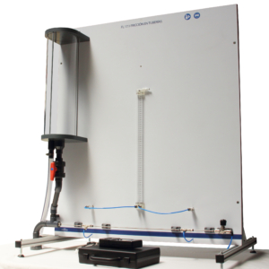
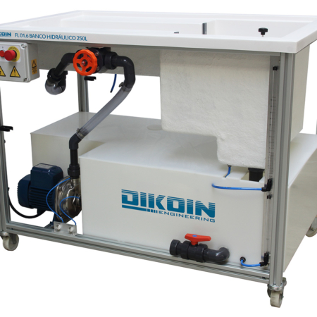
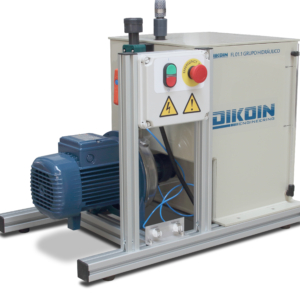
The equipment can be connected to both the bank and the hydraulic power pack with flowmeter.
The manual shows clearly and with a lot of images, the hole process to operate the equipment. The instruction manual explains and shows all the theoretical foundations, as well as all the mathematic expressions used during the experimentation. With the instructions manual, it is delivered a completely solved one, with the data that has to be taken from the equipment during the experiments. This way, the teacher can compare easily if students are doing correctle the different experiments.
All equipment accessories have a detailed description on foot equipment, allowing easy identification of these and providing information at the time of calculation of pressure drop in each and everyone of the accessories.
Measurement and testing of primary load losses that occur on straight sections of various types of pipes, considering the possibility of measuring losses in pipes:
- Different interior diameters, 21.2 and 13.6 mm.
- Different materials.
Checking the relationship between pressure drop and flow velocity in the pipe.
Obtaining pipe roughness:
- galvanized steel
- copper
- etc …
Measurement and verification of secondary load losses that occur in elements of facilities such as:
- Elbows 90 ° short radius.
- Elbows 90 ° long radius.
- 45 ° elbows.
- You straight.
- You tilted.
- Sudden enlargement.
- Abrupt narrowing.
- Gradual widening.
- Taper.
- Gate valve.
- Check valve.
- Valve seat.
- Ball valve.
- Diaphragm valve.
- Diaphragm.
- Venturi.
- Rotameter.
- Filter.
- etc …
Calculation of loss coefficients corresponding “K” to each of the
elements mentioned above.
Use, calculation and setting of various measuring elements, such
as:
- Rotameter.
- Venturi.
- diaphragms; inner diameter 15 mm. and 13 mm.
- Flow metering valve.
- etc …
Check the pressure of work throughout the facility.
Using different types of gauges:
- Water column.
- Electronic differential pressure gauge.
- Bourdon type.
Draw and compute the characteristic of the pump installation.
- Inner diameters:
- Main pipe Øinner = 21.2 mm. ; outer = 25 mm.
- Narrowing / smooth widening.
* Øinner = 13.8 mm. ; Øouter = 16 mm.
- Narrowing / sudden enlargement.
* Øinner = 45.2 mm. ; Øouter = 50 mm.
Manometers:
- Water manometer, range ca 1 m
- Electronic differential pressure gauge (± 7000 mbar)
- Bourdon Manometer, read range 0/25 m ca
- Hand-Bourdon gauge, read range -76 cm Hg / ca 25 m
Gauge lengths between tappings:
- In the straight sections of pipe No. 7 and No. 14 is 1 meter.
- At number section 12 is 0.5 meters.
- Between the end of the fitting gauge shots and there is
always the beginning or 40 mm, except for the following
cases:
* Tappings gauge upstream and downstream of the
diaphragm (3) to 135 mm.
* Tappings upstream gauge widening (9) and down
abrupt narrowing (11) to 125 mm.
* Shot gauge widening / narrowing soft (4-7) to 270
mm.
Venturi:
- Inner diameter of 12 mm throat.
- Inside pipe diameter 21.2 mm.
- Exit cone 7º
- Input cone 21°
Diaphragm 15 mm:
- 15 mm inner diameter narrowing.
- 21.2 mm inner diameter pipe.
Diaphragm 13 mm:
- 13 mm inner diameter narrowing.
- 21.2 mm inner diameter pipe.
- Hydraulics Bench FL 01.4 or Hydraulic Unit FL 01.1